Website powered by

Unreal Tutorial: Using Editor Utilities to Automate Level Design Tasks

Tutorial / 01 January 2022

Unreal's editor utilities allow you to improve and speed up your workflow by automating repetitive steps without having to modify the engine or learn C++. However, the documentation is lacking, so using them requires some patience to figure out how to use them correctly. So I thought it would make sense to share some insights on how to use them. Since there are many types of utilities, this tutorial only covers the actor action utilities, but everything is also applicable to asset action utilities, which work pretty much the same way.

I'm using UE5 for this tutorial, but editor utilities have been part of Unreal for a while now, so all the steps described work the same for Unreal 4 (Editor Utilities were added around version 4.22).

Actor Actions

Actor actions are available in the context menu of an actor placed in a level:
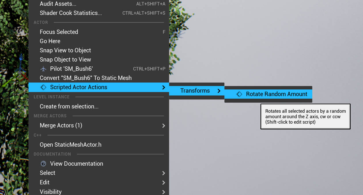
While they can also do other things, the most common use case for them is to modify the currently selected actors in the viewport. Imagine you have a few hundred objects and you need to set property on all of them, but the property needs to vary from actor to actor or is dependent on circumstances like the distance to another object or the assigned material. Doing this manually could take hours, but using an actor action, it's a matter of seconds and has less potential for error.

The action created in this tutorial rotates the selected actors around the Z-axis by a random amount within a customizable range. This is useful to break up the visible repetition.

Creating the Asset
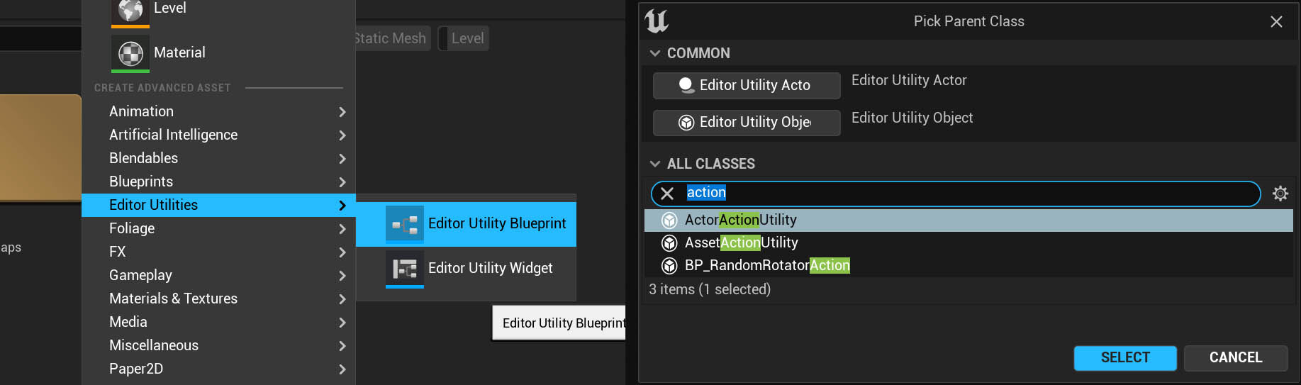
Editor Utilities are listed separately from blueprints in the asset creation menu. You have a wide range of options when selecting the parent class, but most classes are intended for very specific use cases and can be ignored most of the time. There are two action utility classes, one for actor actions and one for asset actions. They work pretty much the same, except that actor action utilities appear in the context menus of actors, and asset actions appear in the context menus of assets in the content browser.

Specifying the Supported Class

After creating the action utility, the first step is to override the GetSupportedClass function. In this case, I set the return value to Actor, but for most actions, you should specify a more specific class so that the action only appears in the context menu if it supports the current actor. Especially if you use a lot of actions, this helps to avoid clutter in the menus and prevents the users from running an action on a light that is intended to modify a mesh, for example.

Creating the Function
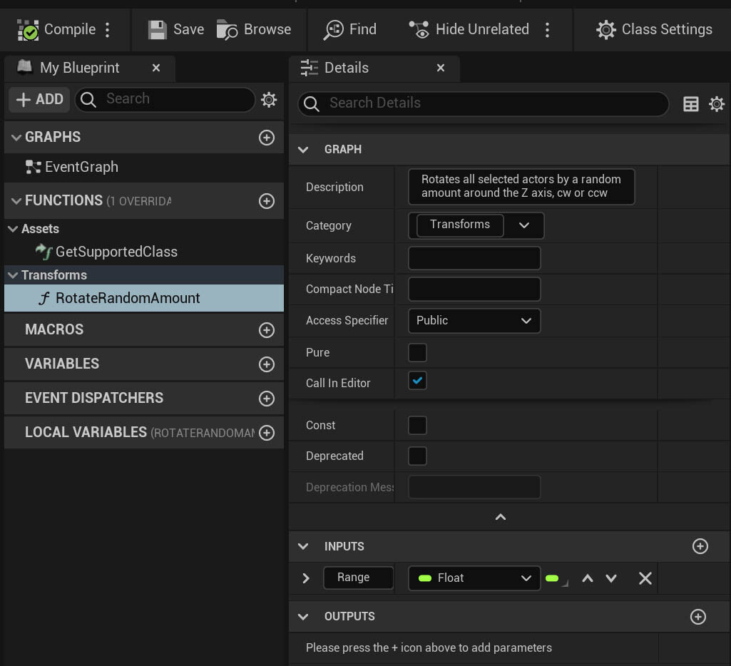
Any function added to the utility that isn't pure and has Call In Editor enabled will appear as an action in the context menu. So if you're creating functions to organize your code, disable Call In Editor. Also, be sure to add a description, it's used to generate the action's tooltip. If you use a lot of different actions, you can also add a category. Multiple actions with the same category will be grouped in the same submenu, making it easier for users to navigate the menus later.

The Function

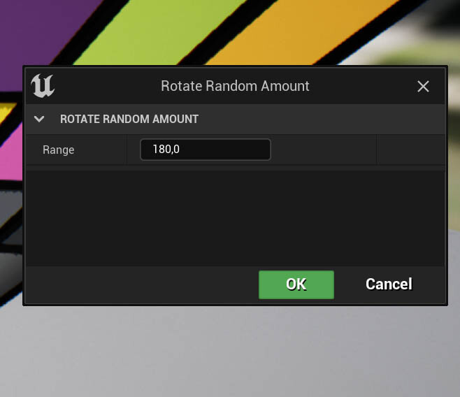
The function for adding the random rotation is quite simple. It gets the selection set, an array containing all selected actors, and uses a for each loop to add a random rotation to the Z-axis. The range of rotations is provided by a float input. When a function is called that uses inputs, a dialog window opens where you can set the values:

The Undo Stack

To make editor tools safer to use, make sure they use Unreal's undo system. To do this, you need to wrap all steps in transactions. A transaction is a list of steps performed during that transaction and the previous state of modified objects. When you undo the transaction, this state is restored. So if you want to make all your changes undoable, you need to call the Begin Transaction node at the start, the Transact Object node for each object you want to modify, and the End Transaction node when everything is done. 

Actor actions are already wrapped in transactions, but unless you tell the undo system to save object states using the Transact Object node, the transaction is empty and discarded. As you can see in the example function, each actor's state is saved before the rotation, therefore the transaction contains changes and shows up in the undo history. Unfortunately, it's just named Blutility Action. Blutility is the outdated name for editor utilities, but it still shows up here and there in the Engine.

For reference, this is how the function would look like if the action wouldn't already be wrapped in a transaction:

This graph produces the same result as the previous one. When transactions are created during another transaction, they are simply added to that one. If this isn't the case, it makes sense to plug something into the context and description inputs, so that the undo step has a name when it shows up in the undo history.

If you encounter problems with the transactions, the undo history is a useful debugging tool. Just enable the Show transactions details setting and you can see the lists of modified objects and even the properties changed on those actors:

Running the Action

After saving your utility, you can run the action on any number of actors to add some variation:

While this is a rather simple example, actions can perform complex tasks and save you a lot of time.

Maintenance

If you use action utilities a lot, there are a few ways to make working with them easier:

  • Keep all your action utilities (and editor utilities in general) in a folder separate from your game assets.
  • Use a naming convention that tells you that this asset is an action utility. All editor utilities share the same asset type, so without a naming convention you won't be able to tell their class immediately.
  • If you haven't managed to maintain a solid naming convention, you can also search for ParentClass==ActorActionUtility in the content browser.
  • To make editing actions easier, you can press Shift while clicking on an action's menu entry 


If you enjoyed this article or found it useful, please share it with others! If you have any comments, questions, or feedback, please post them below. To get informed about new articles, follow me on Artstation, on Mastodon or Bluesky.

You can also find this article on my WordPress blog.

Tutorial: Adding a PBR validation view mode to Unreal

Tutorial / 21 December 2021

I recently found this Twitter thread by David Torkar, in which he explains how to add custom view modes to Unreal using post-process materials. So I tried it out and added a PBR validation mode, something which I felt was always missing from Unreal.

What are valid base color values?

According to the usually used references, the lower limit for the base color values should be somewhere around 30-50 in a 0-255 sRGB range. The upper limit is usually set at 240. For metal reflectance values (which is technically something else than the base color, even though we use the base color input for it), the range should be 180-255.

While values can technically be out of this range, our goal is usually to replicate reality, and there aren't really that many materials in the real world that are outside of this range. Even when creating stylized content, keeping all colors in a valid range is a good idea to make sure materials behave predictable under identical lighting conditions. If you choose to leave the range, make sure you have a good reason to do so.

The Validation Material

The material is quite simple. Since it's not used at runtime, I didn't bother too much with optimization and added the remapping and sRGB->linear conversion for the range parameters. From my experience, working in the 0-255 range is more intuitive for most people, since you don't have to deal with decimal numbers. There are three colors used to mark values below, in, and above the valid ranges. At the end of the material, the shading model used for the current pixel is checked, and for unlit surfaces, the original color is kept. This helps with the orientation in the level since the sky is still visible this way.

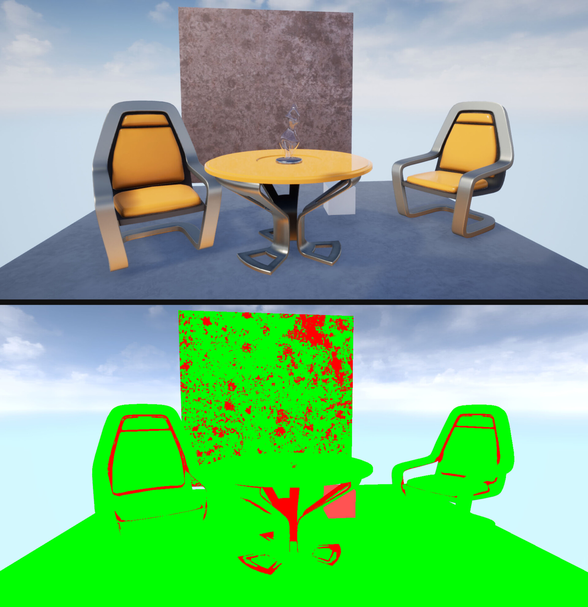
When enabling the material using a PP volume, it behaves as expected. Both the dark areas in the chairs' crevices and the grime on the metallic surface in the background are marked as too dark, the white box is marked as too bright.

Adding the View Mode

Now that the material works as intended, move it to a directory where it doesn't get mixed up with the rest of the game, something like
/Game/ViewModes/PP_PBRValidation_BaseColor.

Now, to add the view mode, open DefaultEngine.ini (located in the Config folder in your project directory) and add a new section:

[Engine.BufferVisualizationMaterials]BaseColorValidation=(Material="/Game/ViewModes/PP_PBRValidation_BaseColor .PP_PBRValidation_BaseColor ", Name=LOCTEXT("BCValidationMat", "Base Color Validation"))

After restarting the editor, a new entry appears in the Buffer Visualization menu:


Other Materials

Using custom post-process materials, you can also display other useful information. These two materials visualize the clear coat and clear coat roughness values, which is useful when fine-tuning car paints:

Known Issues

All materials described above are jittering when used with TAA enabled, since TAA slightly offsets the image each frame. This helps to smooth the image over several frames, but since the PP materials are applied after the tone mapping, they aren't affected by the TAA, which would smooth out the jittering. If it really annoys you, you can just disable TAA while working with the view modes.
You can also change the location of the material to be before the tone mapping, but if you're using any color grading, LUTs, etc. in your game, these get applied during the tone mapping and can change the look of the view mode.
As you may already have noticed, using post-process materials isn't a replacement for proper view modes, since you're restricted to the information provided in the GBuffer. Still, it's a nice trick to be aware of.


If this post was enjoyable or useful for you, please share it! If you have comments, questions, or feedback, post them below. To get new posts, follow me on Artstation.
You can also find this article on my WordPress blog.
Tutorial - Disabling obsolete shadow casters in Unreal

Tutorial / 21 December 2021

A while back, I watched this talk about performance optimizations in Gears 5, and I was intrigued by their process for detecting objects that don't cast visible shadows.
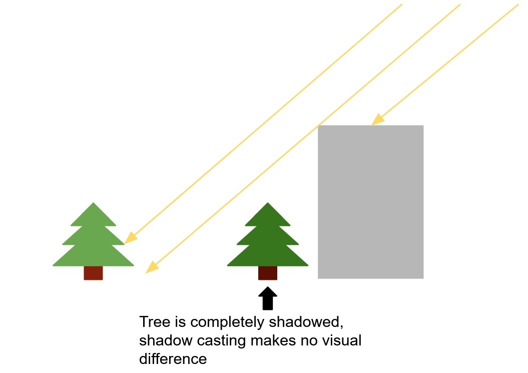
Basically, in outdoor scenes, you usually only have one relevant light source, the sun:
Any mesh that doesn't have a clear line of sight to the sun is in the shadow. No light will reach it, so shadow casting will have no visual impact. Therefore, shadow casting can be disabled for this mesh.
Theoretically, you could avoid rendering the shadow for this mesh by adding occlusion culling to the shadow rendering, but in most cases this would probably actually worsen performance, since it's expensive to do this at runtime, and as long as the environment is static (which is the case for many games), it's also not necessary, we can just do it once in the editor.
So, I decided to implement this optimization using blueprints. My method is a bit simpler than the method mentioned in the video linked above and is therefore more conservative, but depending on the level content, it can still improve performance noticeably. And since it worked so well for me, I decided to write this tutorial for other people who are struggling with the performance cost of shadow rendering (and who isn't?).

Use Cases

If you want to add this implementation to your own game, make sure you'll benefit from it. There are some conditions that your content should meet:

  • If you have a day-night cycle in your game, this optimization won't work. You could adjust the blueprint to check if an object is lit by the sun for every sun position throughout the day, but the number of objects that are never reached by the sun is probably quite small.
  • For baked lights, this optimization doesn't apply. Disabling shadows on objects used for light baking reduces the baking time but doesn't improve the performance of the game at runtime. Instead, it degrades the quality of the indirect lighting.
  • If parts of your level geometry are destructible or can move during gameplay, you will need to adjust the blueprint to ignore moveable/destructible objects. If your level is almost entirely destructible, the savings you get from this method may not be worth the effort.
  • If other light sources can be added at runtime (maybe the player can equip a flashlight), some meshes won't cast shadows when lit by them. I imagine it might be possible to split the 'Cast Shadow' setting into two, one for directional lights and one for all other light types, but that's another topic for another day.

While the implementation is mostly blueprint-based, I also made a small engine change to make the tool easier to use. It's not strictly necessary for the blueprint to work, though, so you can skip this part if you're using a precompiled version of the engine.

How it works

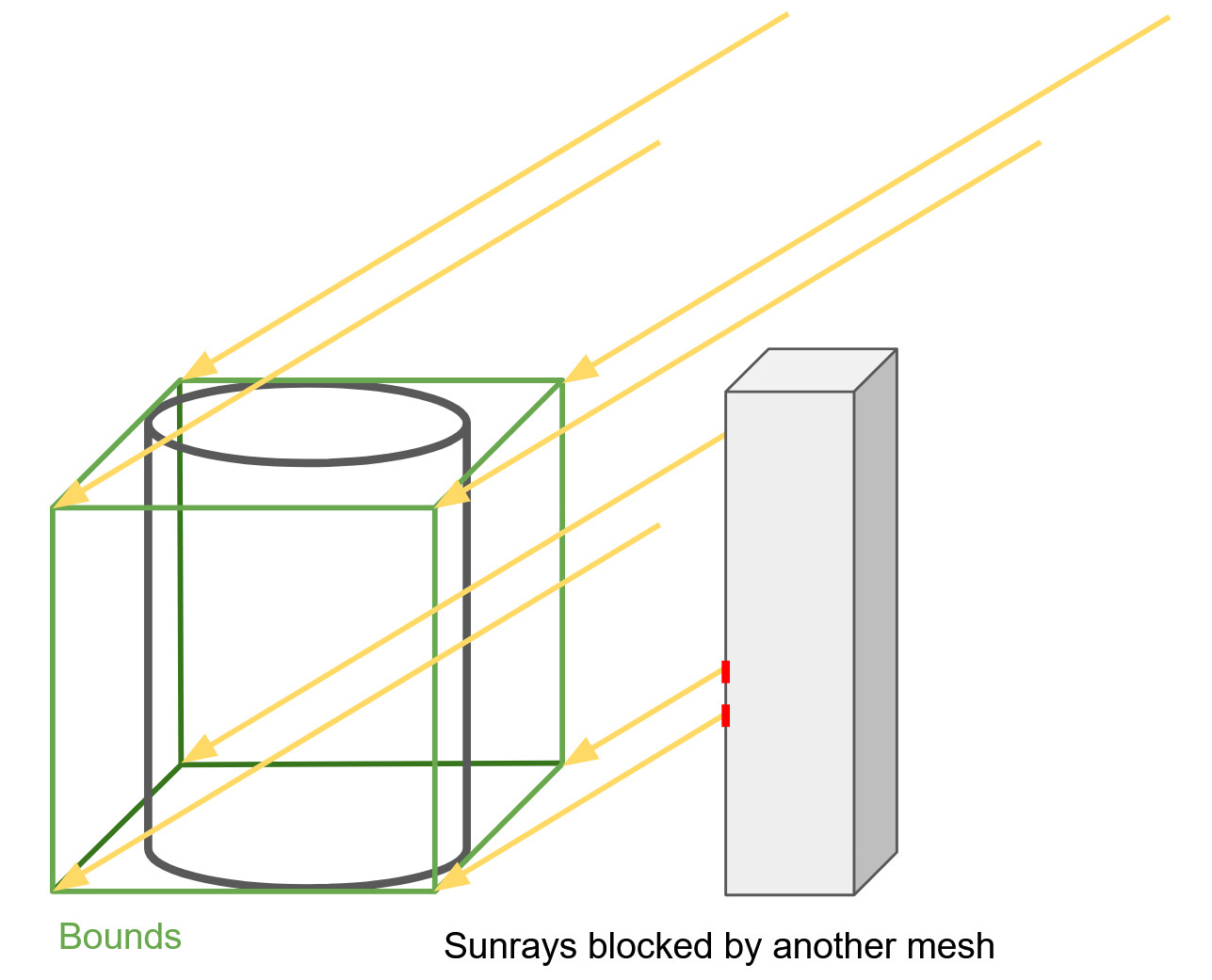
To check if an object casts a shadow, the blueprint iterates over all shadow-casting static mesh components in the level. For each mesh, it does 8 line traces towards the sun, using the corners of the bounding box as starting points. If at least one of the traces doesn't hit a shadow-casting mesh, the mesh is lit by the sun and must cast a shadow. Since the bounding box is used instead of the actual mesh, there will be some false positives, so some objects will be considered lit when they aren't. Theoretically, there could also be cases where all traces hit shadow-casting geometry while the center of the object is still lit, but so far, this situation hasn't come up in any of the levels I've used for testing.

Creating the Blueprint

1. Create an Editor Utility Blueprint and select EditorUtilityActor as parent class. This way you can be sure that the actor won't be included in your packaged game. Place the actor in a level that contains some static meshes and a sun to test it on.

2. In the blueprint you need to create 6 functions. The first one is called  'Disable Obsolete Shadows':

This function is called in the construction script and uses the other functions to perform all the necessary steps. First, it gets the sun's light vector using the 'Get Light Vector' function. Then it iterates over all the actors in the level, gets the static mesh components and calls 'Set Shadow Based on Light Vector' on them. The cast to the Instanced Foliage Actor makes sure we don't perform these steps on foliage, since we can't control shadow on individual instances.

Note: As you can see in the screenshot, the light vector is stored in a local variable. All variables in this blueprint are local, which makes it much easier to keep track of which variable has which value at any point in the graph.

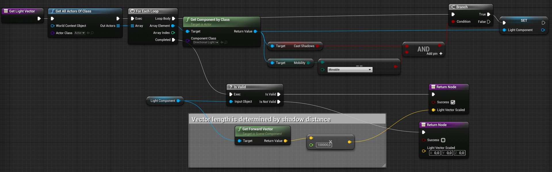
3. The 'Get Light Vector' function is quite simple. It finds all directional light source components in the level, and if a component is both shadow-casting and dynamic, it returns its forward vector (The light direction) multiplied by 100000 (which is just a very high magic number).

4. 'Set Shadow Based on Light Vector' checks for each static mesh component if it's lit by the sun and sets the shadow accordingly:

If a mesh component passes the checks, the shadow casters are searched for for each vertex of the bounding box.
If a ray doesn't hit a shadow-casting mesh, the loop is broken and the shadow is enabled.

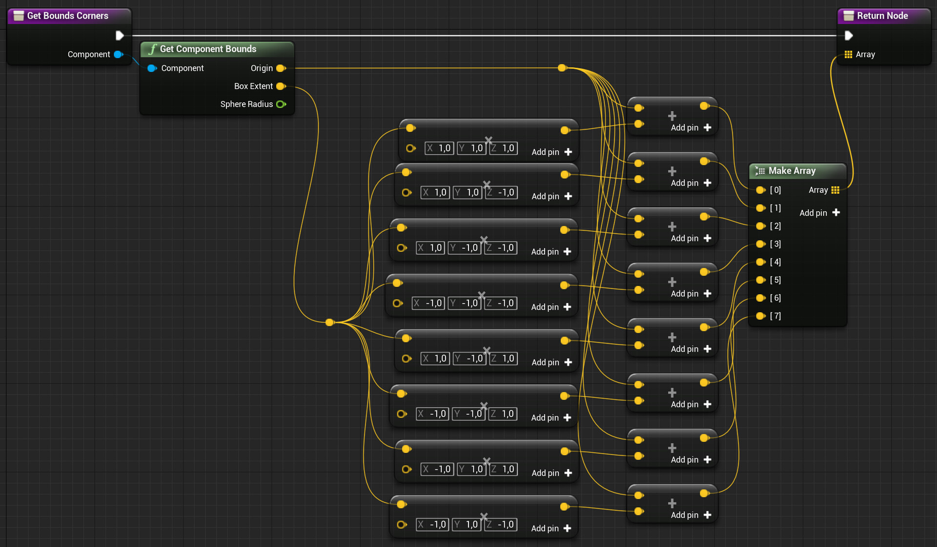
5. 'Get Bounds Corners' is used to get the starting points for the line traces. This is not the most exciting or elegant function:
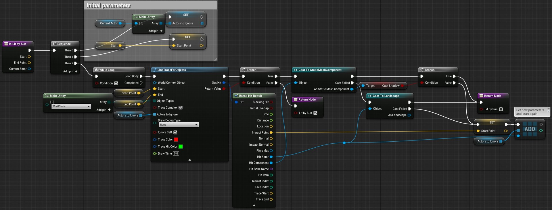
6. The 'Is Lit By Sun' function does the actual line traces. Yes, plural, because one isn't always enough. The line trace can also hit blocking volumes or meshes that aren't casting shadows. In this case, we need to do a new line trace, starting at the hit position and excluding the hit actor. This loop is repeated until we reach the end of the line trace or find a shadow-casting mesh. 

Each time a hit is detected, the component is cast to a static mesh component, and if the cast is successful, the 'cast shadow' setting of that component is checked. If a shadow is cast, 'Lit By Sun' is false - at least for this line trace. If the hit component is not a static mesh, the hit actor is cast to a landscape. Technically, the blueprint should also check whether the landscape casts shadows, but for my personal project I'm assuming that all landscapes cast shadows, so I skip this step.

7. That's it! After compiling the blueprint and placing it in a level, you're done. There are a few steps to refine it:
At least for initial testing, you may want to add some logic to the blueprint to count the number of meshes on which shadows get disabled by this logic, to see if the optimization works as intended and saves some draw calls. You can also use the options in the line trace node to draw some debug lines.
Depending on your projects, you may also want to extend the blueprint to also consider spline meshes or even skeletal meshes if you're using skeletal meshes for your environments. You can also extend it to include spotlights or point lights.

The Engine Change

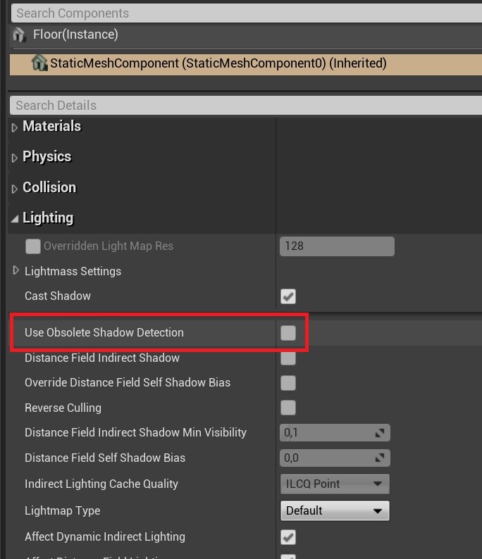
As mentioned earlier, I slightly modified the engine to have a setting for each static mesh component to disable this automatic system. This change is fairly trivial if you're familiar with C++. If you're not, the biggest hurdle is downloading the engine's source code and successfully compiling it. There are plenty of resources for this on the web, so I won't cover it here. Once you have your engine built, all you need to do is open
...\Engine\Source\Runtime\Engine\Classes\Components\StaticMeshComponent.h
In the class body of UStaticMeshComponent, add the marked lines:

The comment in the first line seems trivial, but Unreal uses these comments to generate tooltips in the editor, so don't skip it. Then the UPROPERTY macro is called. This macro makes sure that the variable declared in the next line can be used in the editor.
After compiling and starting the editor, the new setting appears in the static mesh component details:


The Results

In order to have a representative comparison with a level that isn't built in a way that exaggerates the effectiveness of this optimization, I used KK Design's Modular Ruins Kit, available on the Unreal Marketplace. The example level contains several cliffs and ruins that cast shadows on several clutter items on the ground, so there should be some shadows that can be disabled by this system.
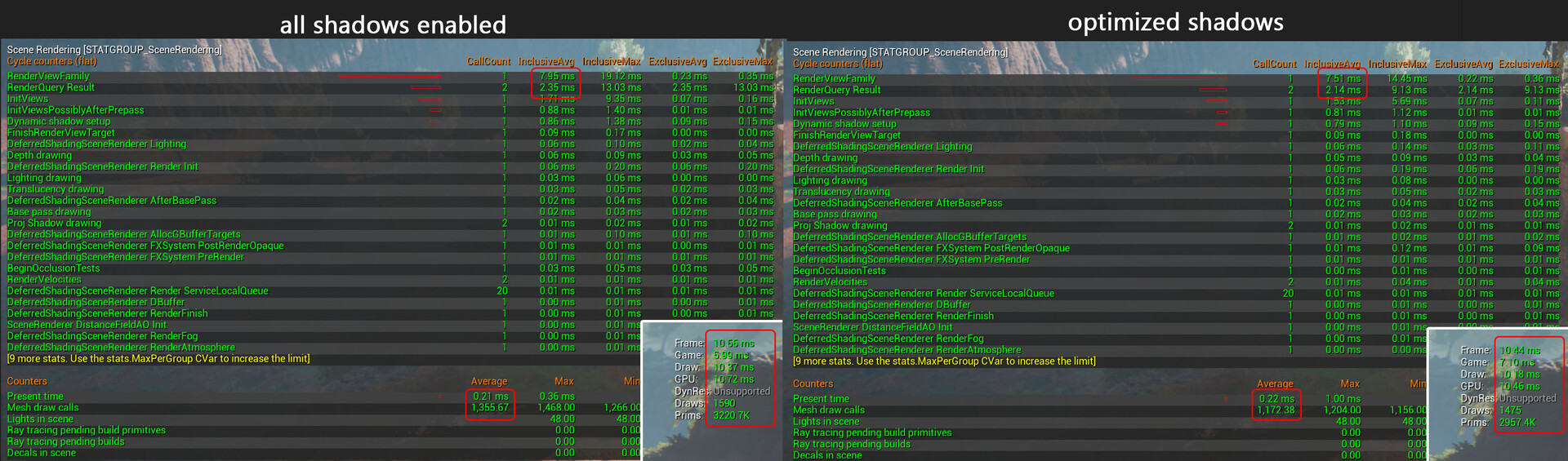
These are the results after placing the blueprint in the level:
While the performance difference isn't huge, the optimization saves 0.2-0.3ms on both CPU and GPU. Note that there is no visual difference, and since the system is fully automatic, there are no adjustments necessary later on when the content changes or new levels are added. Depending on your game, you'll likely see consistent performance improvements throughout your outdoor levels.

Known Issues

When using contact shadows, there are some cases where this optimization can make a visual difference. Contact shadows aren't limited by the shadow draw distance used for the CSM shadows, so for smaller objects, they are helpful to still draw at least some shadows in the distance. Contact shadows aren't rendered for non-shadow-casting meshes in 4.26+, so disabling shadows removes these shadows as well.
So if an object is far away from the camera, it's not covered by the CSM shadows due to the restricted draw distance. As a result, the contact shadows missing now make an actual difference. This isn't a real problem in the levels I've used this technique in so far, but it's something to be aware of.


If you enjoyed this article or found it useful, please share it with others! If you have any comments, questions, or feedback, please post them below. To get informed about new articles, follow me on Artstation, on Mastodon or Bluesky.

You can also find this article on my WordPress blog.